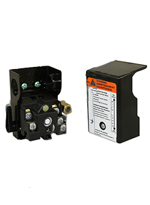
Ingersoll Rand 56289671 Pressure Switch (OEM)
Replacement for Ingersoll Rand 56289671 Pressure Switch (OEM), Models SS3L3 / SS5L5 / SS5N5, Serial # CBV110752 and Higher
Replacement for Ingersoll Rand 56289671 Pressure Switch (OEM), Models SS3L3 / SS5L5 / SS5N5, Serial # CBV110752 and Higher 56289671- Brand Name: Ingersoll Rand
- Part Number: 56289671
- Check Stock
CUT-IN & CUT-OUT: The cut-out (compressorshut-down) is the pressure at which the switch contacts open, andthe cut-in (compressor restart) is the pressure at which the switchcontacts close.
ADJUSTMENT CONTROLS: All pressure switches have arange adjustment control. Some pressure switches also have adifferential adjustment control. On switches without a differentialadjustment control, the span between cut-in and cut-out pressurelevels switches is factory set for 40 ± 4 PSIG and cannot beadjusted.
NOTE: Some pressure switches are equipped with anon-off lever used to open and close the electrical contacts insidethe switch. THIS LEVER IS NOT ADIFFERENTIAL ADJUSTMENT CONTROL. The pressureswitches with the on-off lever do not have a differentialadjustment control.
ADJUSTMENT PROCEDURES (SWITCHES WITHOUTDIFFERENTIAL ADJUSTMENT CONTROL):
1. Remove the pressure switch cover.
2. Adjust the range by turning the range adjustment screwclockwise (in) to increase the cut-out point or counter-clockwise(out) to decrease the cut-out point.
NOTE: One full turn changes the settingapproximately 2-6 PSIG.
3. Replace cover, reconnect power supply and start thecompressor.
4. Note the pressure gauge reading at which the compressor cutsout.
5. Repeat adjustment procedure if necessary.
ADJUSTMENT PROCEDURES (SWITCHES WITH DIFFERENTIALADJUSTMENT CONTROL):
1. Remove the pressure switch cover.
2. Set the cut-in pressure with the range adjustment nut. Turn thenut clockwise (in) to increase the pressure or counter-clockwise(out) to decrease the pressure.
NOTE: One full turn changes the settingapproximately 2-6 PSIG.
3. Set the cut-out pressure with the differential adjustment. Turnthe differential adjustment nut clockwise (in) to increase thepressure or counter-clockwise (out) to decrease the pressure.
NOTE: One full turn changes the settingapproximately 2-6 PSIG.
4. Replace the cover, reconnect the power supply and start theunit.
5. Note the pressure gauge reading at which the unit cutsout.
6. Repeat the adjustment procedure if necessary.
The minimum possible differential is approximately 20% of cutoutpressure. It is advisable to have as wide a differential aspossible to avoid frequent starting and stopping of the unit. Notethe pressure gauge reading at which the unit cuts-out andre-establish this point if necessary. Note the interaction betweenthe range and differential adjustments, i.e., if the cut-out isincreased, the differential will also increase, or if thedifferential is narrowed, the cut-out will be reduced, etc.These
factors must be considered when adjusting the switch andcompensated for accordingly.
PRESSURE SWITCH INSTALLATIONPRECAUTIONS:
Diaphragm leaks can occur if a new pressure switch is installedimproperly. During installation of a new pressure switch, do nottighten the pressure switch by turning the switch body by hand.Putting sideways pressure on the switch body puts stress on thebody-to-diaphragm connection and may cause later failure due tovibration, temperature expansion, or pressure.
In addition, do not use the pressure switch assembly as a handlewhen moving the compressor. This places stress on thebody-to-diaphragm connection and can distort internalcomponents.
Failure can occur by putting undue stress on the unloader bodywhile tightening the unloader tubing with a wrench. Do not adjustthe orientation of the pressure switch by turning the entireassembly with a wrench placed on the unloader connection.
The image shown in this listing is for illustrative purposes only and does not reflect the actual configuration or components of the product.
| Compressor Type | : | Reciprocating |
| Product Type | : | Genuine/OEM |
- Meets Or Exceeds OEM Specifications
- Cost Effective Solution To OEM Parts
- Using Aftermarket Parts Will Not Void Your Warranty
- OEM Names And Part Numbers Are For Reference Only


 Add To Favorites List